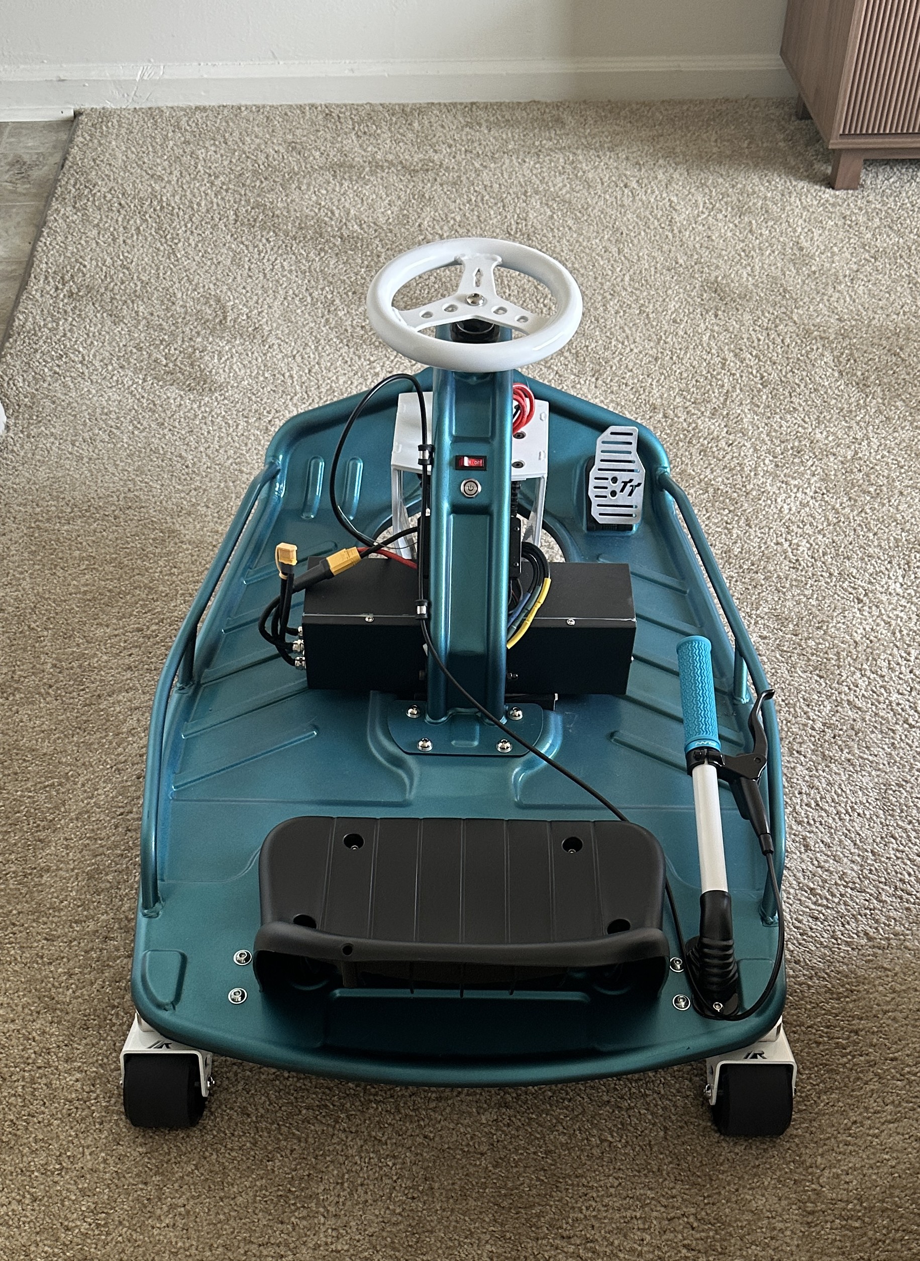
Electric Vehicle Motor Controller (VESC)
Assembling, debugging, and modifying a high-power field-oriented control drive for three-phase brushless DC motors

Overview
Originally developed by Benjamin Vedder, VESC (Vedder Electronic Speed Controller) is an open-source motor control platform designed to control electric motors with high performance, flexibility, and efficiency.
The VESC ecosystem includes both hardware and software. Controllers are configured and monitored using VESC Tool, which provides motor setup, tuning, data logging, firmware updates, and real-time diagnostics.
Hardware Architecture
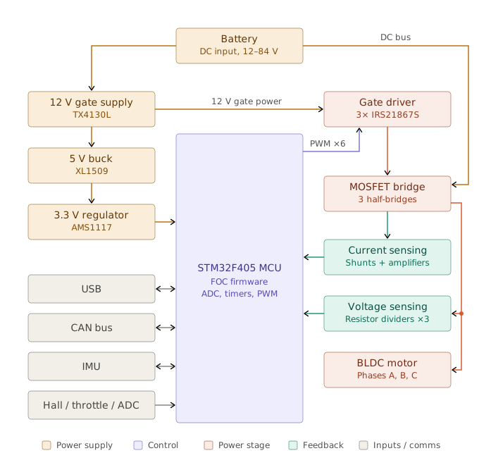
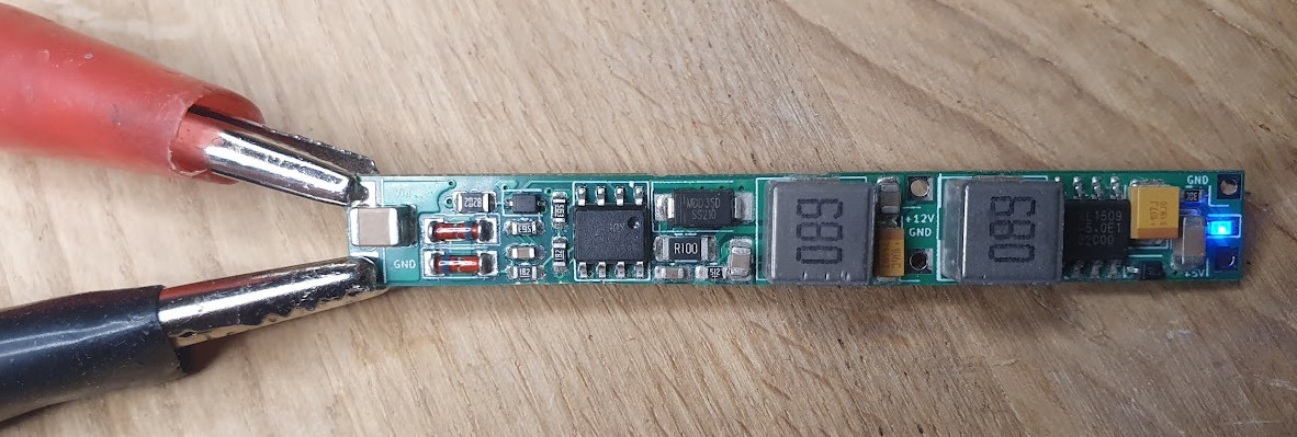
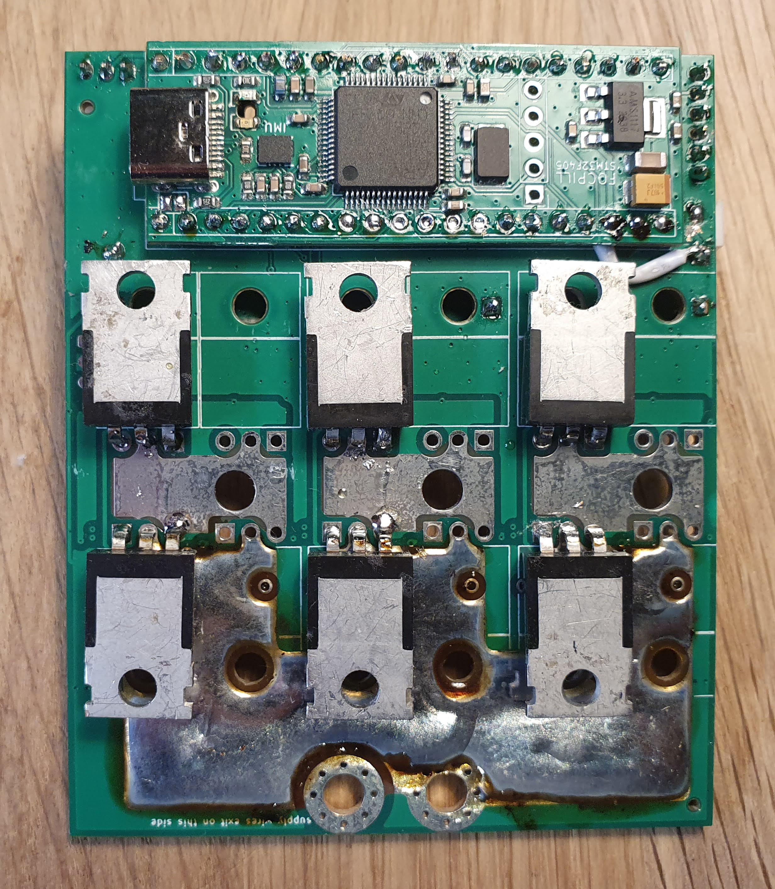
Hardware is divided into three main subsystems: an STM32 microcontroller module, a DC/DC power supply, and a MOSFET power stage.
Together, these modules handle control, voltage regulation, and power delivery to the motor.
01 — STM32 MICROCONTROLLER MODULE
STM32F405 Control Board
The STM32F405 serves as the controller’s main processor and runs the VESC firmware. It receives current and voltage feedback, performs the field-oriented control calculations, and generates the PWM signals used to command the inverter.
Its onboard peripherals provide ADC sampling for analog measurements and communication through USB, UART, and CAN. These interfaces support functions such as VESC Tool configuration, motor detection, diagnostics, and communication with external devices.
02 — POWER SUPPLY MODULE
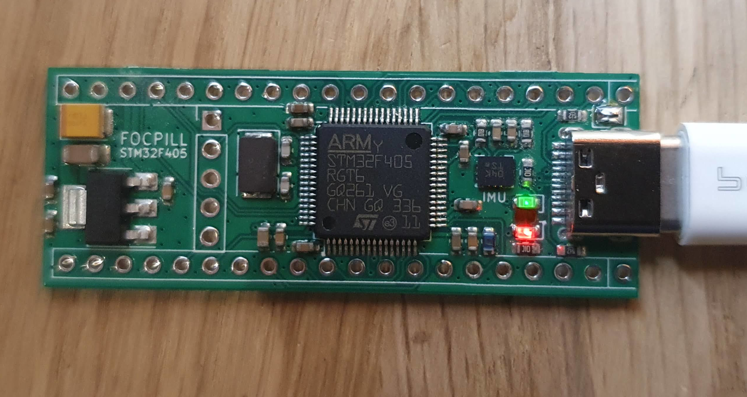
DC/DC Buck Converters
The power supply module converts the main DC input into the lower regulated voltages required by the controller electronics.
Switching buck converters generate a 12 V rail for circuitry such as the MOSFET gate drivers and a 5 V rail for low-voltage electronics. The microcontroller module further regulates its supply to 3.3 V for the STM32 and associated components.
This allows the control circuitry and high-power inverter to operate from the same main power source while using the voltage levels appropriate for each subsystem.
03 — MOSFET POWER STAGE
Three-Phase Inverter
The MOSFET power stage converts the DC bus voltage into the three controlled phase outputs that drive the motor. Each phase uses a half-bridge made from high-side and low-side MOSFETs.
Gate-driver circuitry translates the STM32’s PWM commands into the gate signals required to switch the MOSFETs. Varying the switching duty cycles controls the voltage and current applied to each motor phase.
Current-sensing circuitry measures the phase currents and returns that information to the STM32 for closed-loop control. DC-link capacitors support the inverter by supplying high-frequency switching current and reducing voltage ripple on the DC bus.
My Contribution
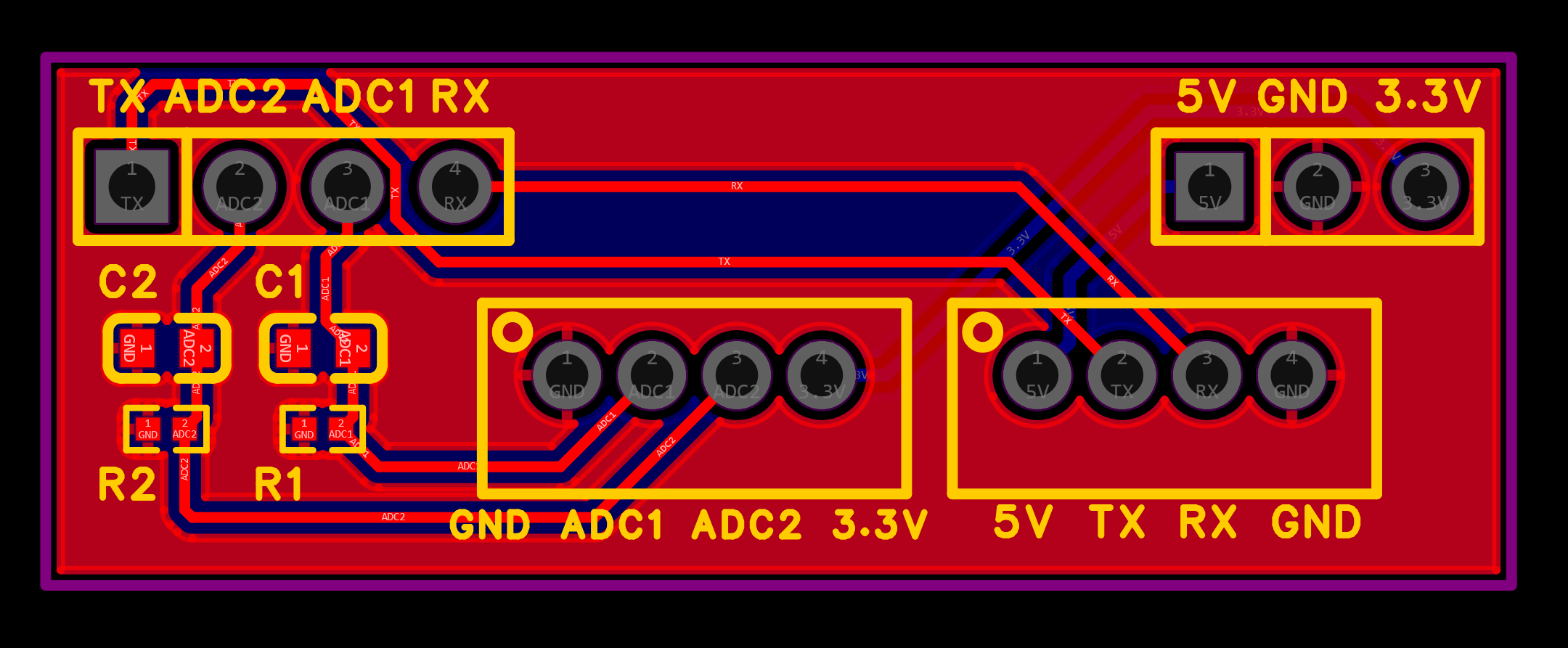
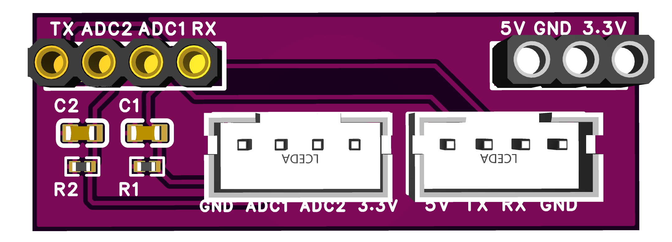
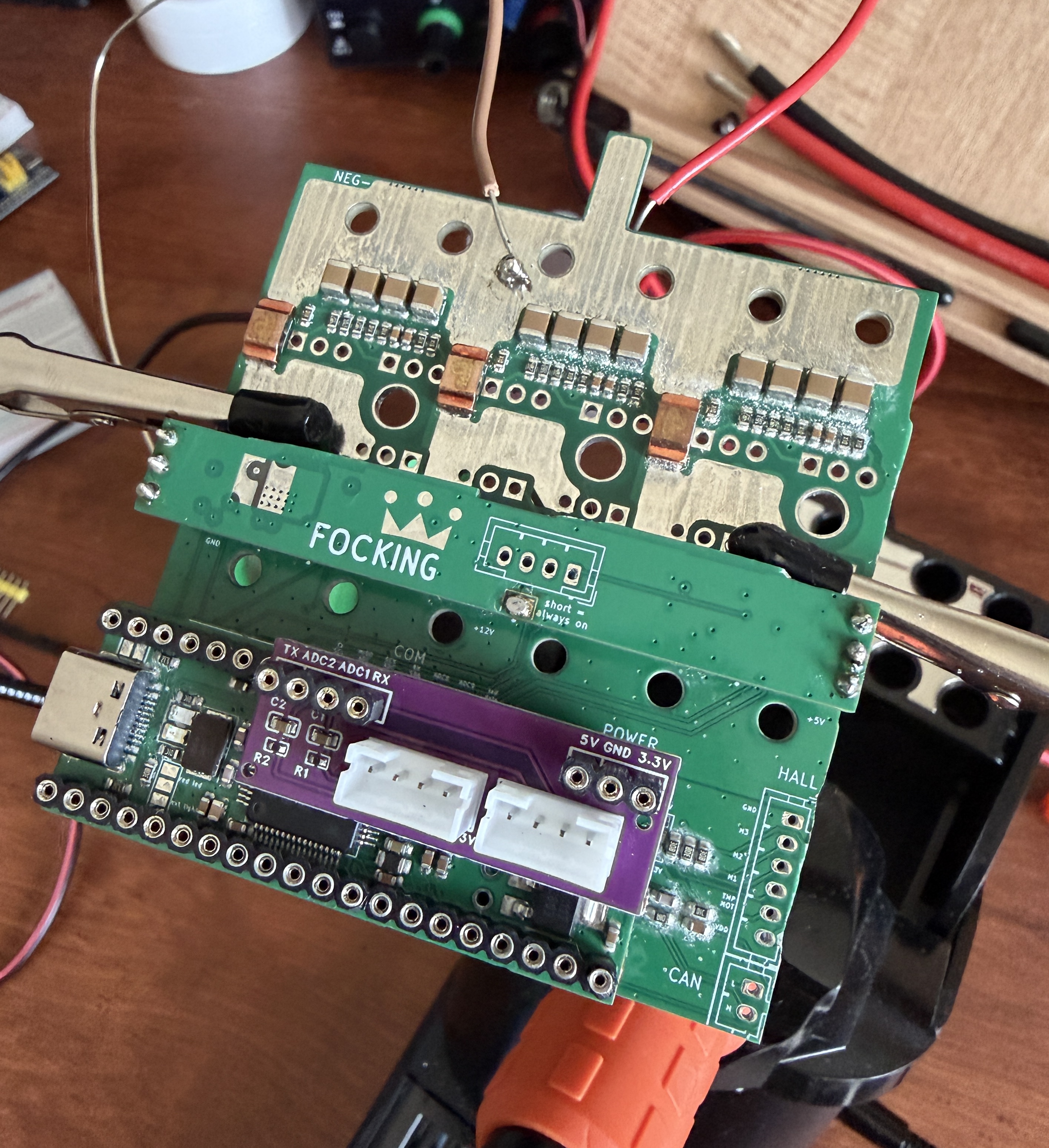
I designed a custom expansion board that adds Bluetooth connectivity to the controller and filters its two analog inputs before they reach the microcontroller.
Problem
ADC2 was randomly triggering regenerative braking and kill-switch behavior even though the throttle mapper itself looked stable. The input was picking up noise and the firmware was reading it as a real command.
Solution
A 10 kΩ pulldown resistor and a 1 µF capacitor from each ADC input to ground.
The 10 kΩ resistor pulls the ADC input toward 0 V whenever nothing is actively driving it. An unconnected ADC pin floats, and a floating pin reads whatever noise it happens to pick up — which is exactly how a stray reading turns into a phantom throttle or brake signal. The pulldown gives the pin a defined resting value instead.
The 1 µF capacitor shunts fast voltage spikes to ground. Together with the source and pulldown resistance it forms a low-pass filter, so the voltage the ADC samples is a much steadier version of the real signal rather than one carrying every transient from the inverter.
Wireless connectivity
The open-source controller did not include onboard Bluetooth, so configuration with VESC Tool initially required a USB connection. The expansion board adds a BLE module to the controller's UART interface, enabling wireless connection to the VESC mobile app for configuration, live monitoring, and parameter tuning from a phone.
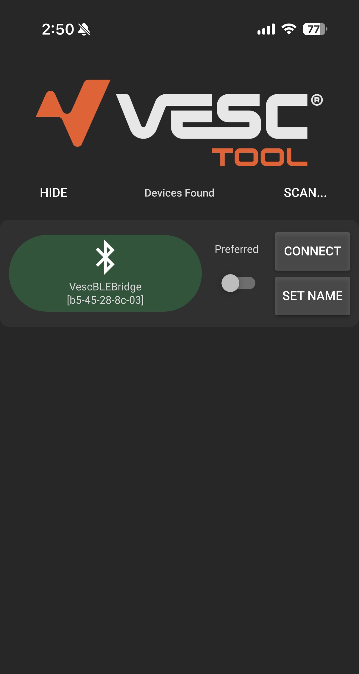
VESC in action!